


SOFTWARE
FIRMWARE

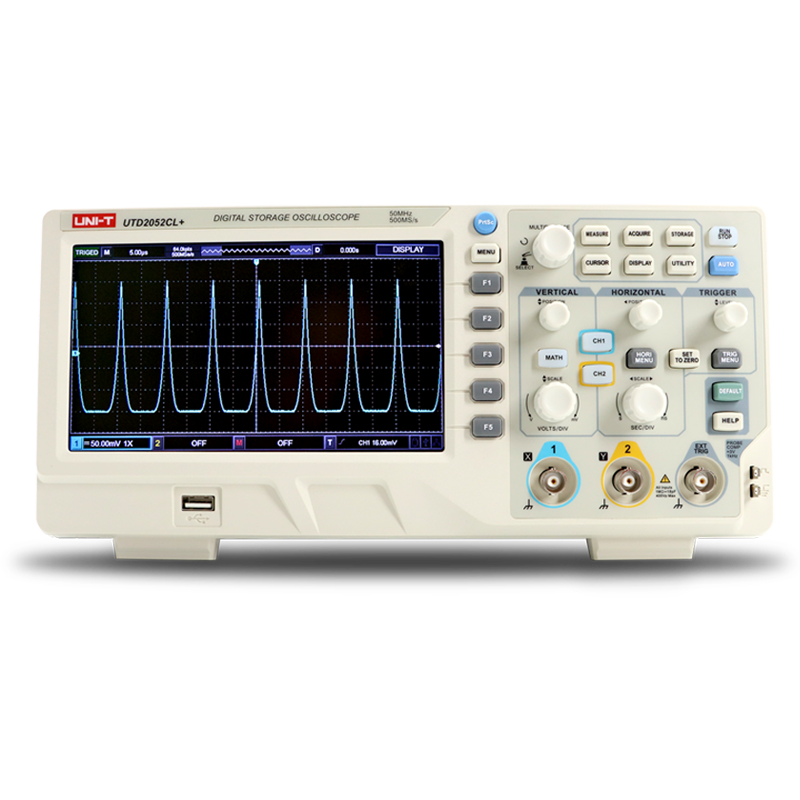
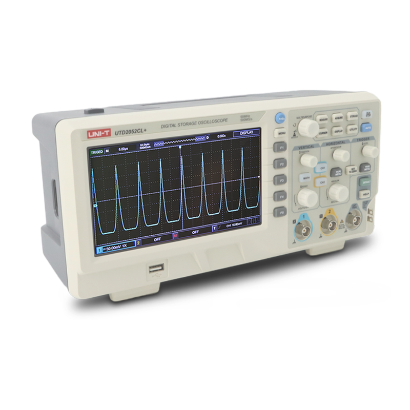
 UTD2000CL+ Data Sheet EN
UTD2025&2052CL Datsheet EN
UTD2072&2152CL Datesheet EN
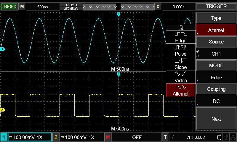
UTD2025&2052CL User's Guide EN
UTD2072&2152CL User's Guide EN
UTD2000CL+/CL User's Guide EN
UTD2072&2152CL Programming Manual EN
UTD2000CL+ Data Sheet EN
UTD2025&2052CL Datsheet EN
UTD2072&2152CL Datesheet EN
UTD2025&2052CL User's Guide EN
UTD2072&2152CL User's Guide EN
UTD2000CL+/CL User's Guide EN
UTD2072&2152CL Programming Manual EN 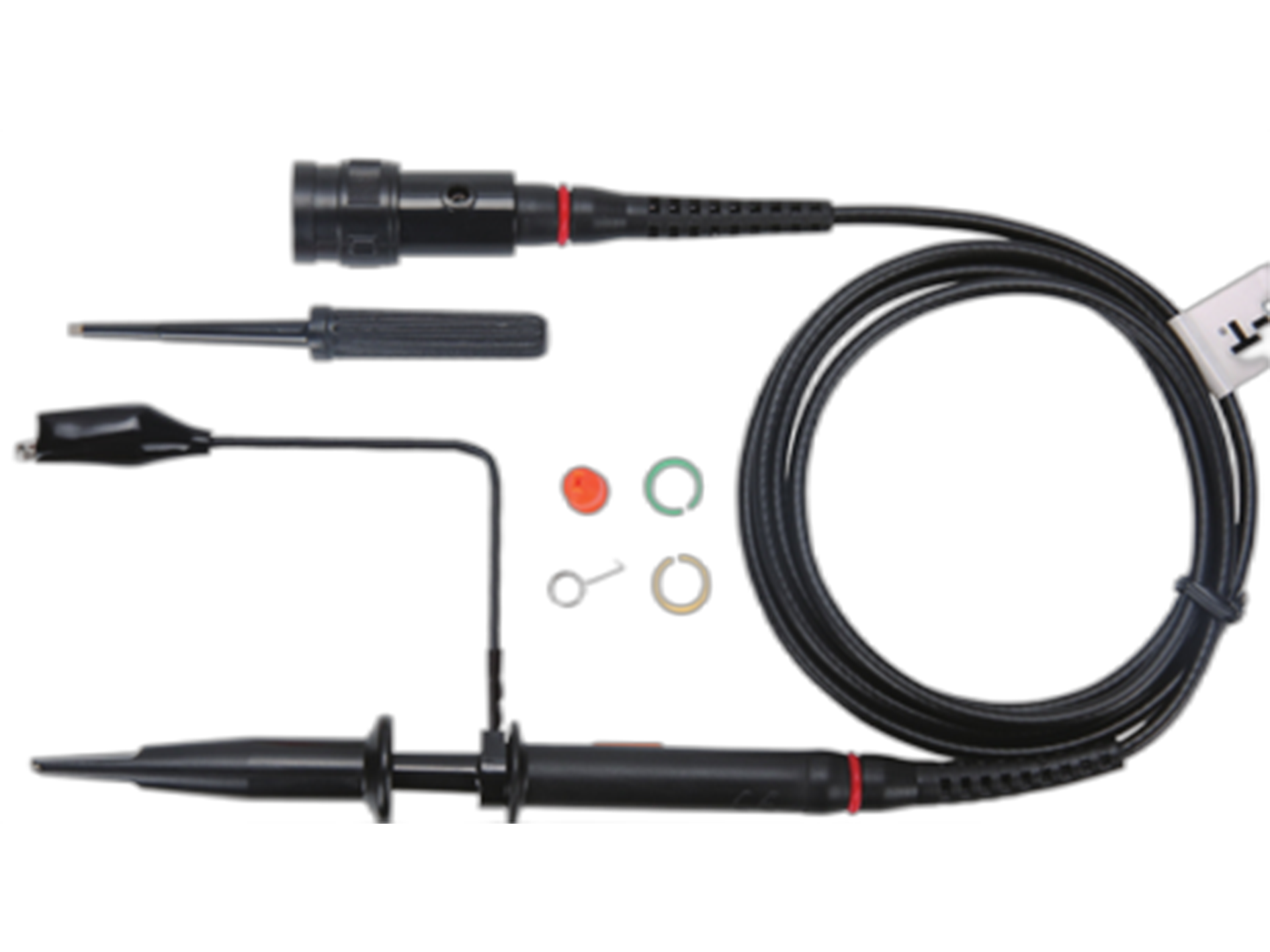
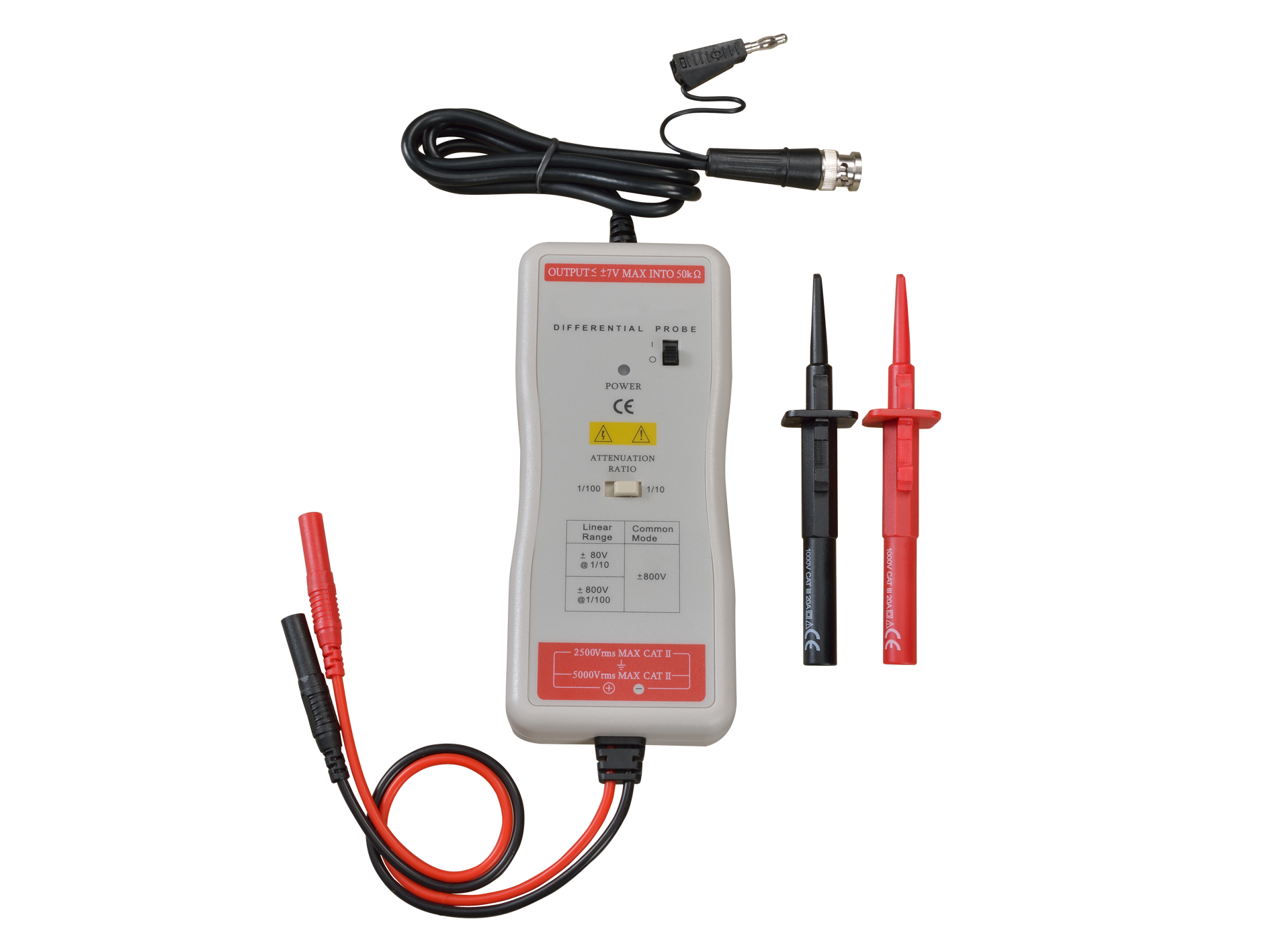


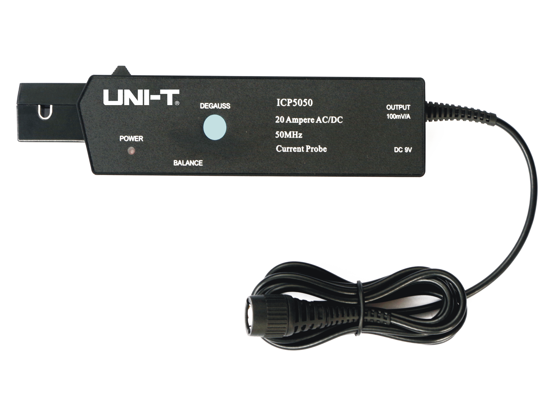
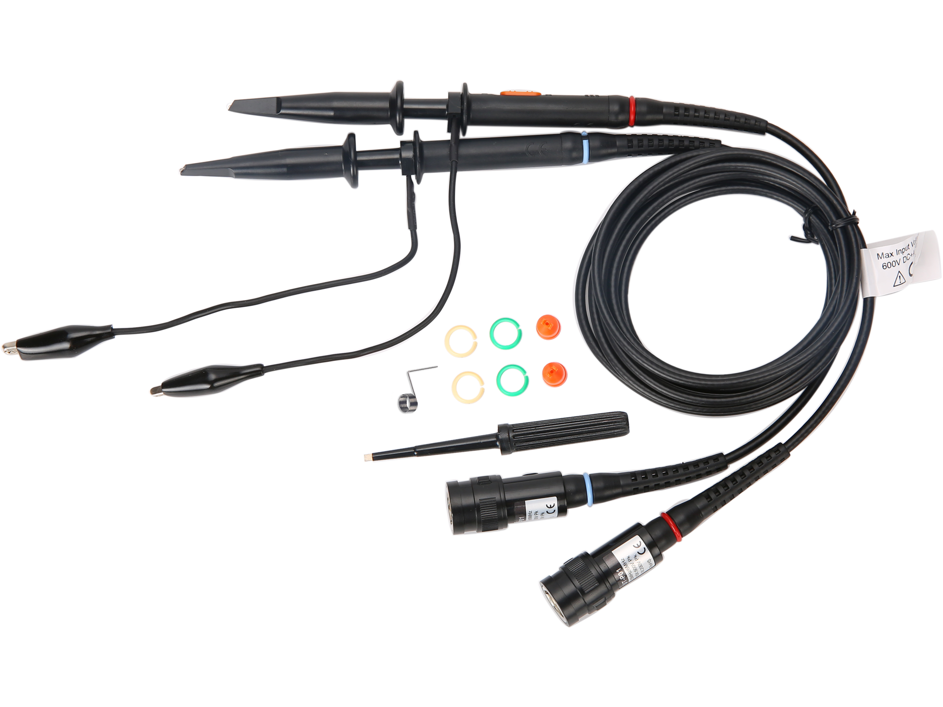
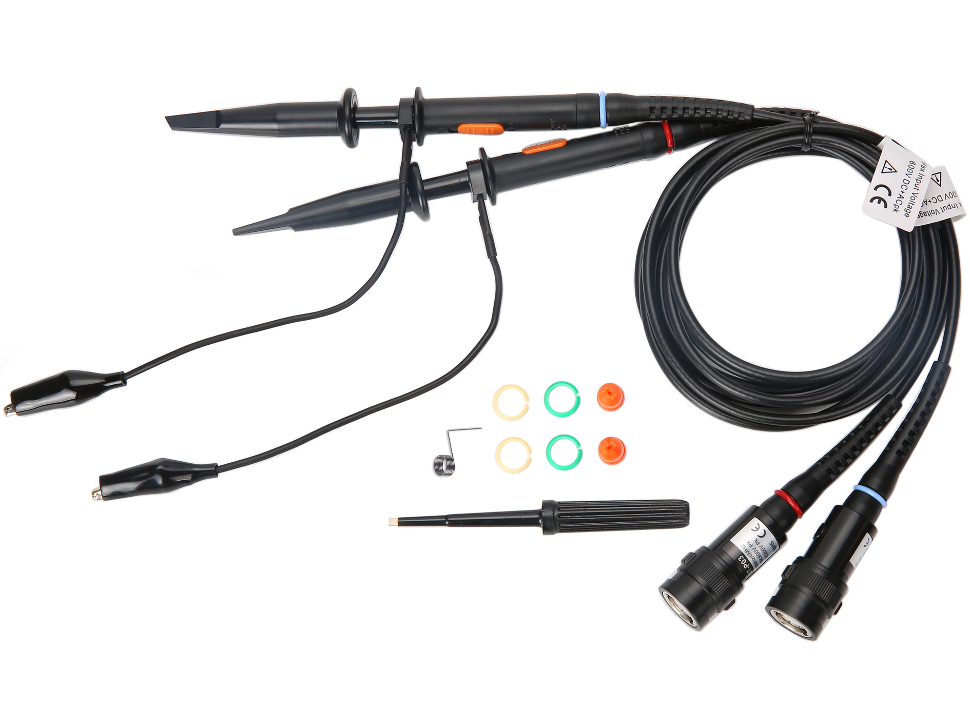
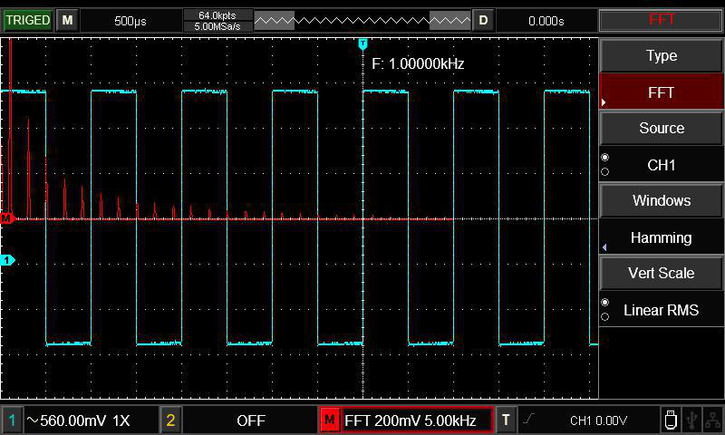
 UT-P4100A
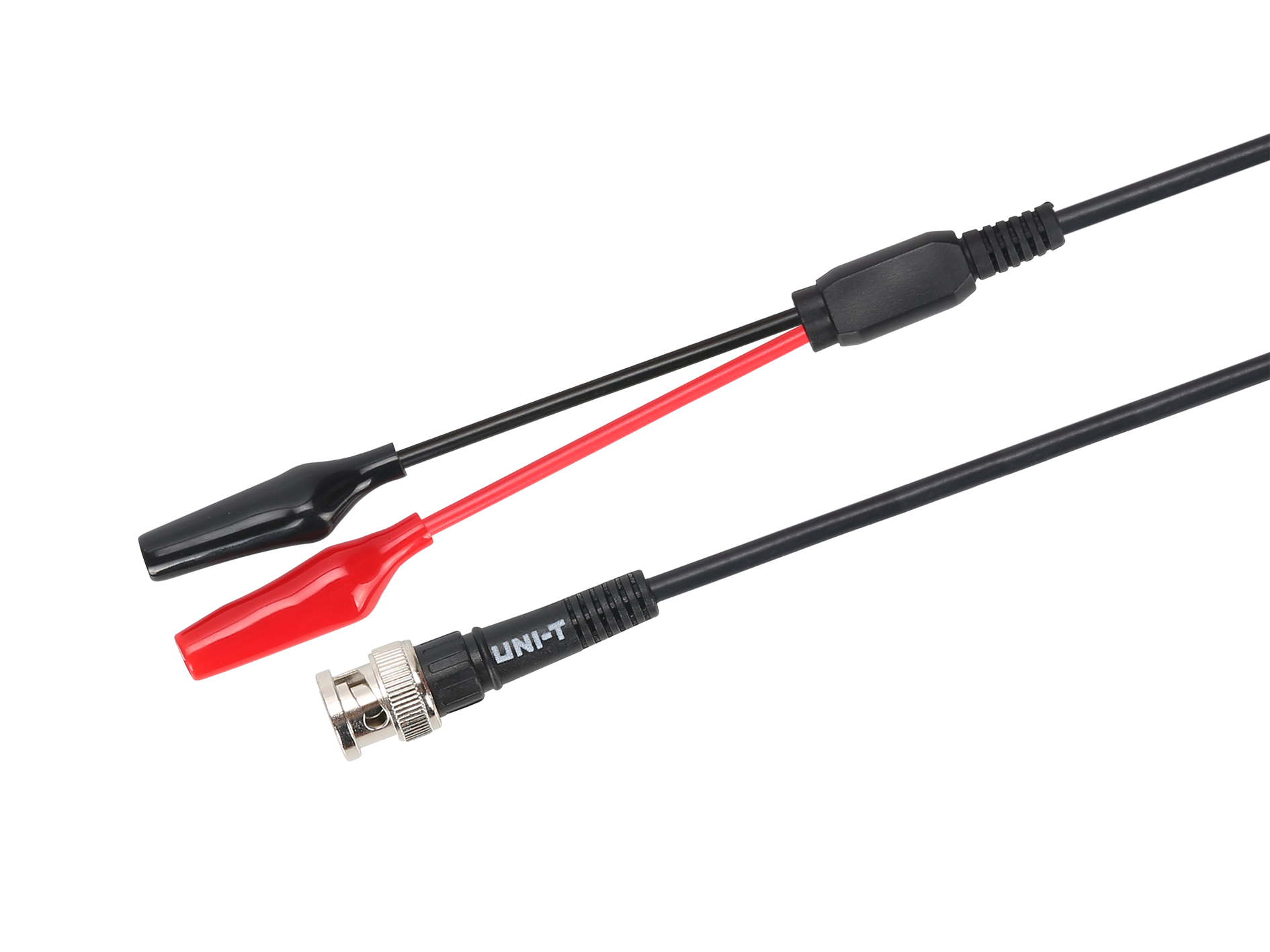
 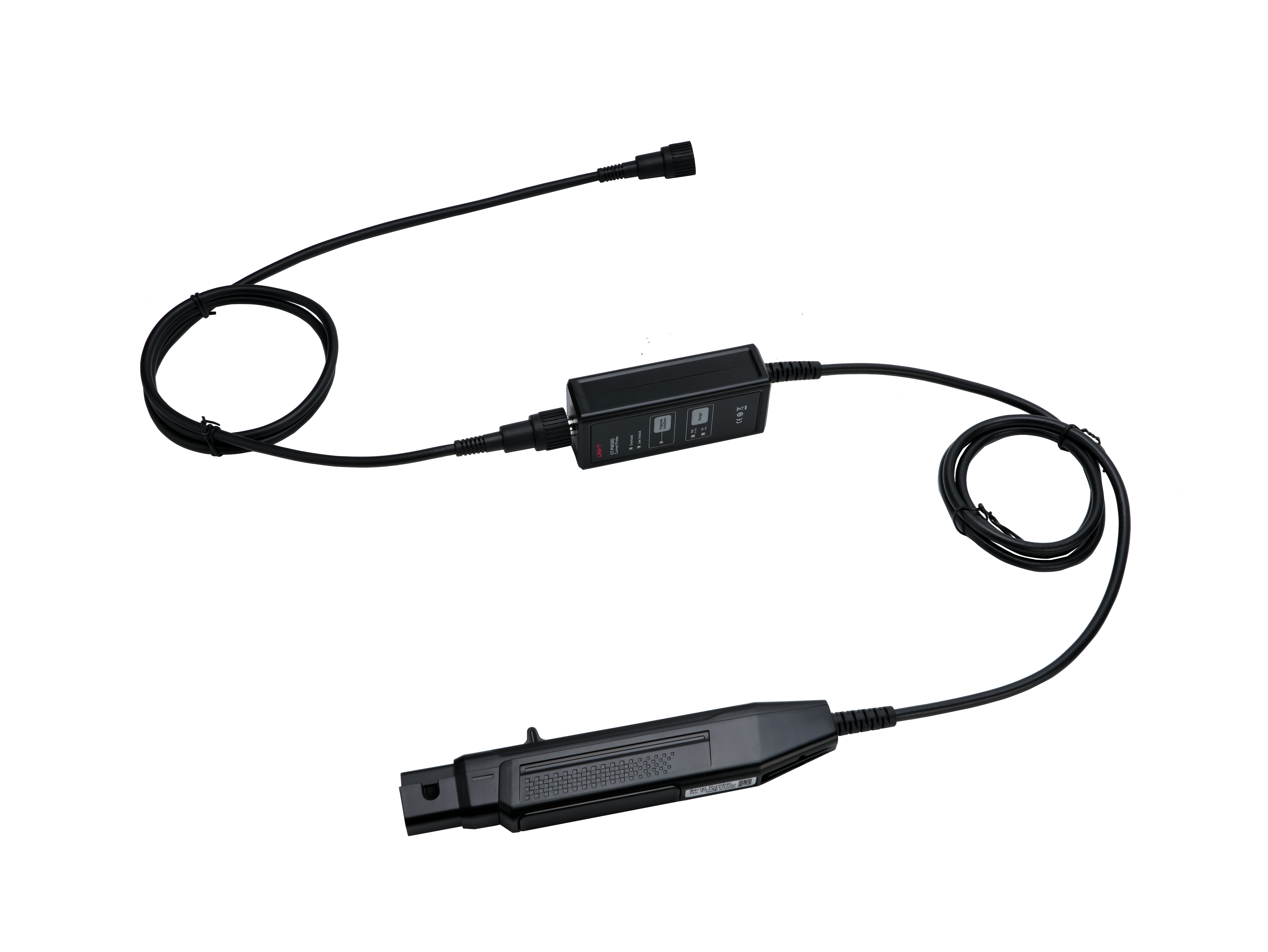 UT-P4030D
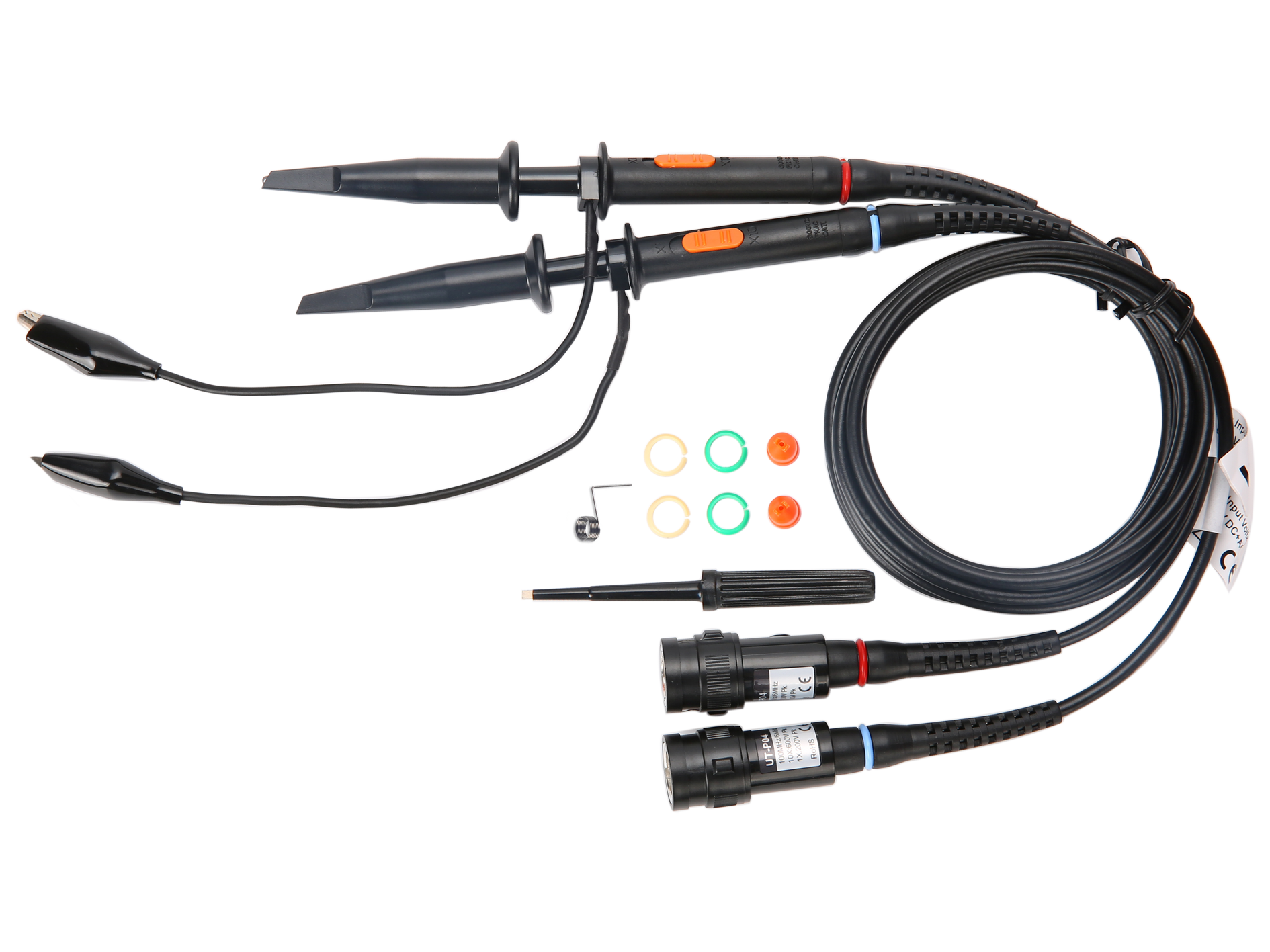
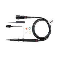
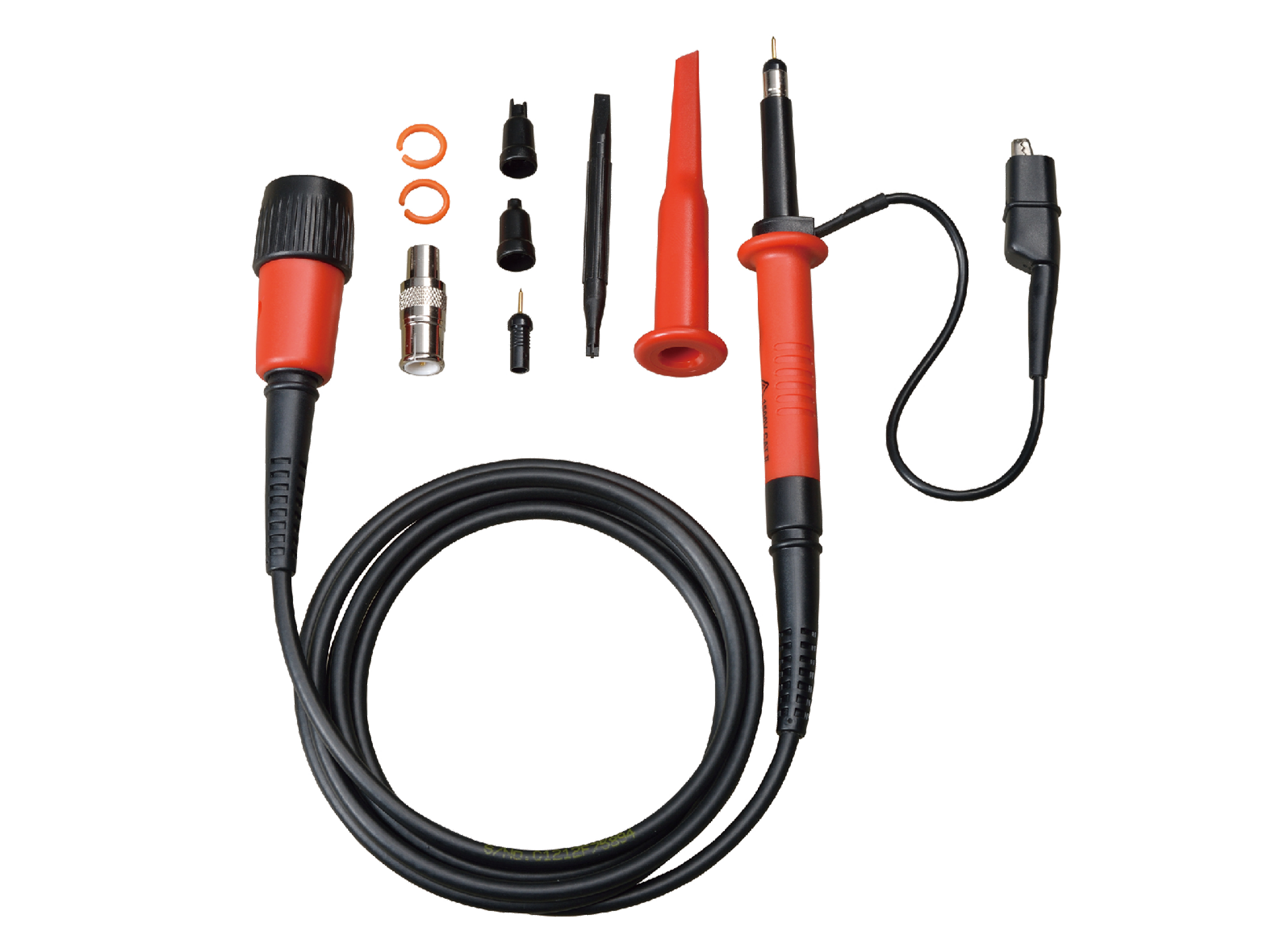
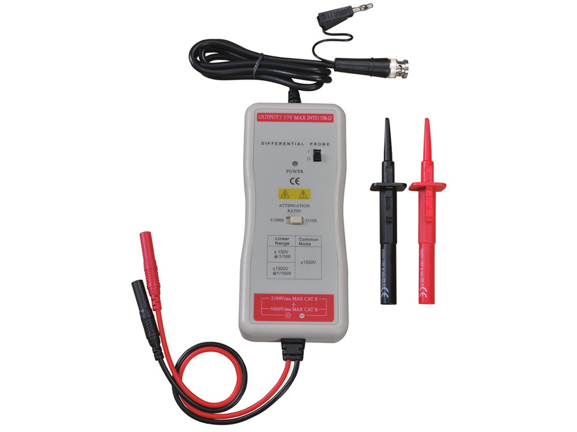
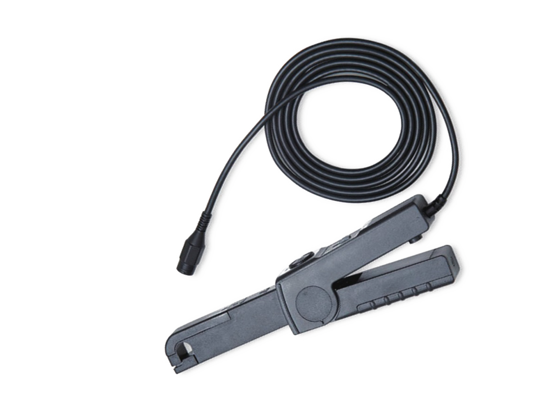
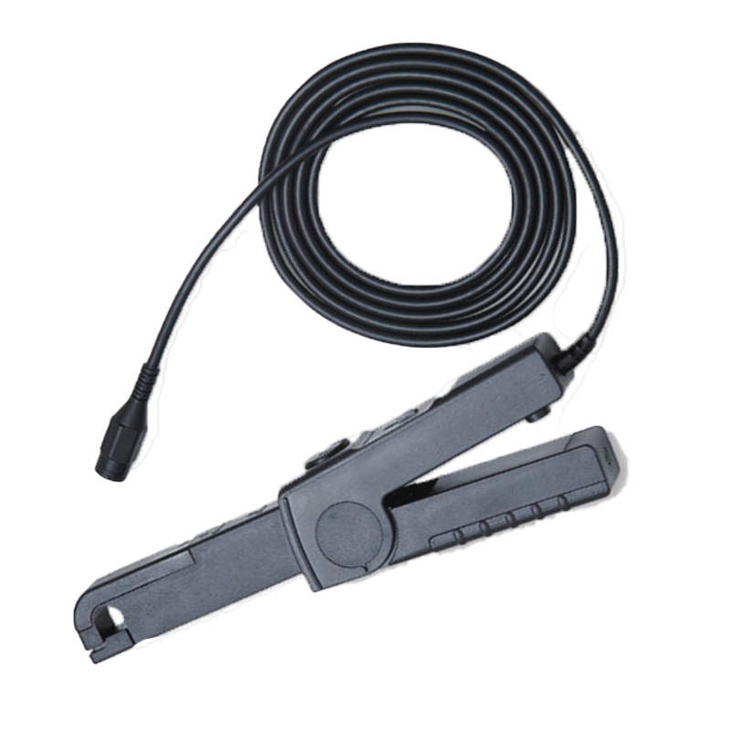
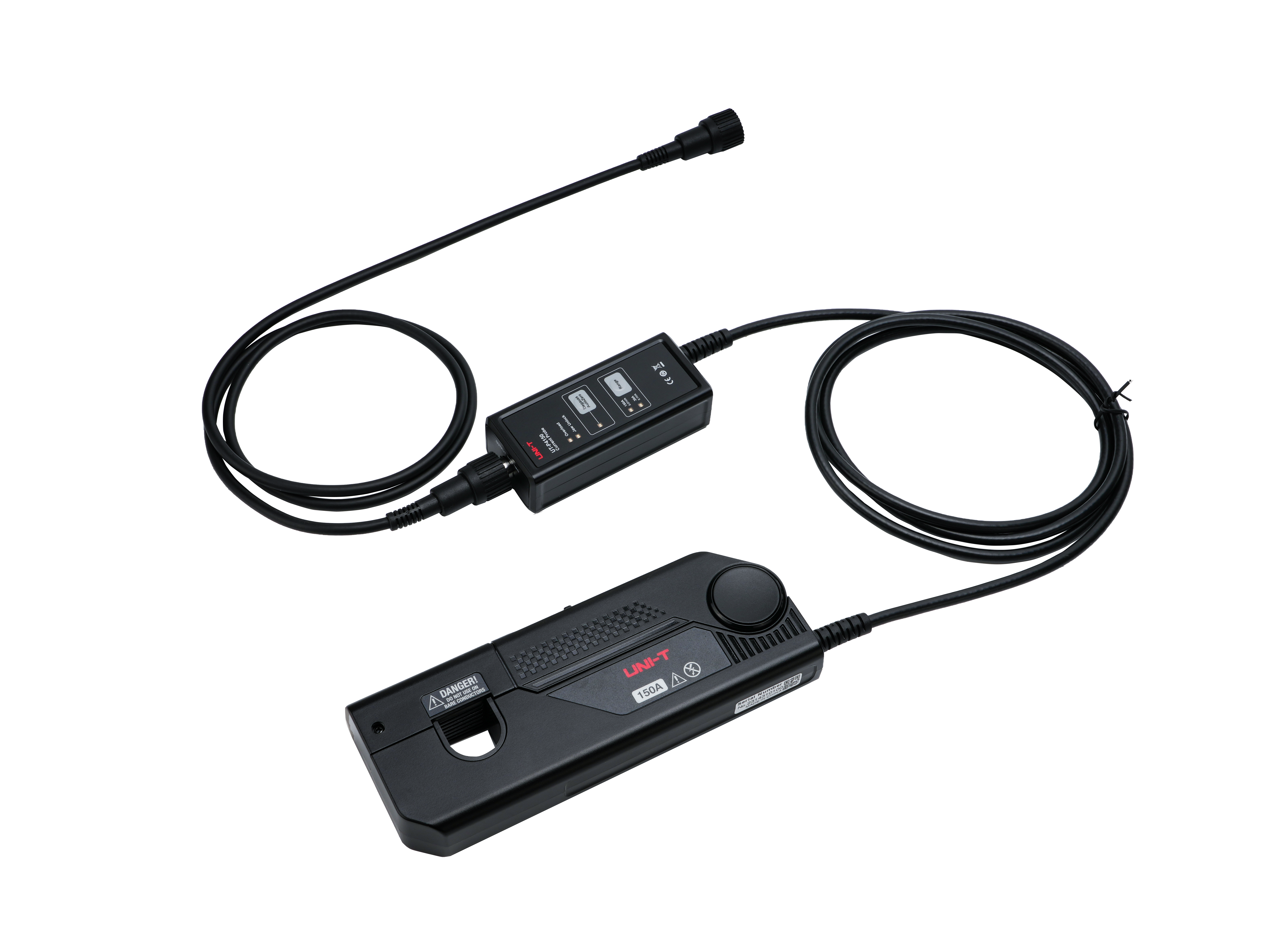 UT-P4150
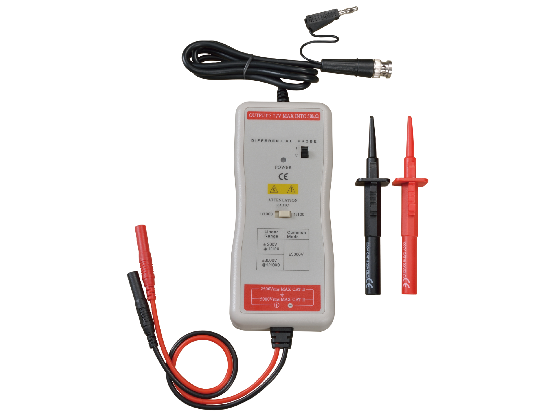
 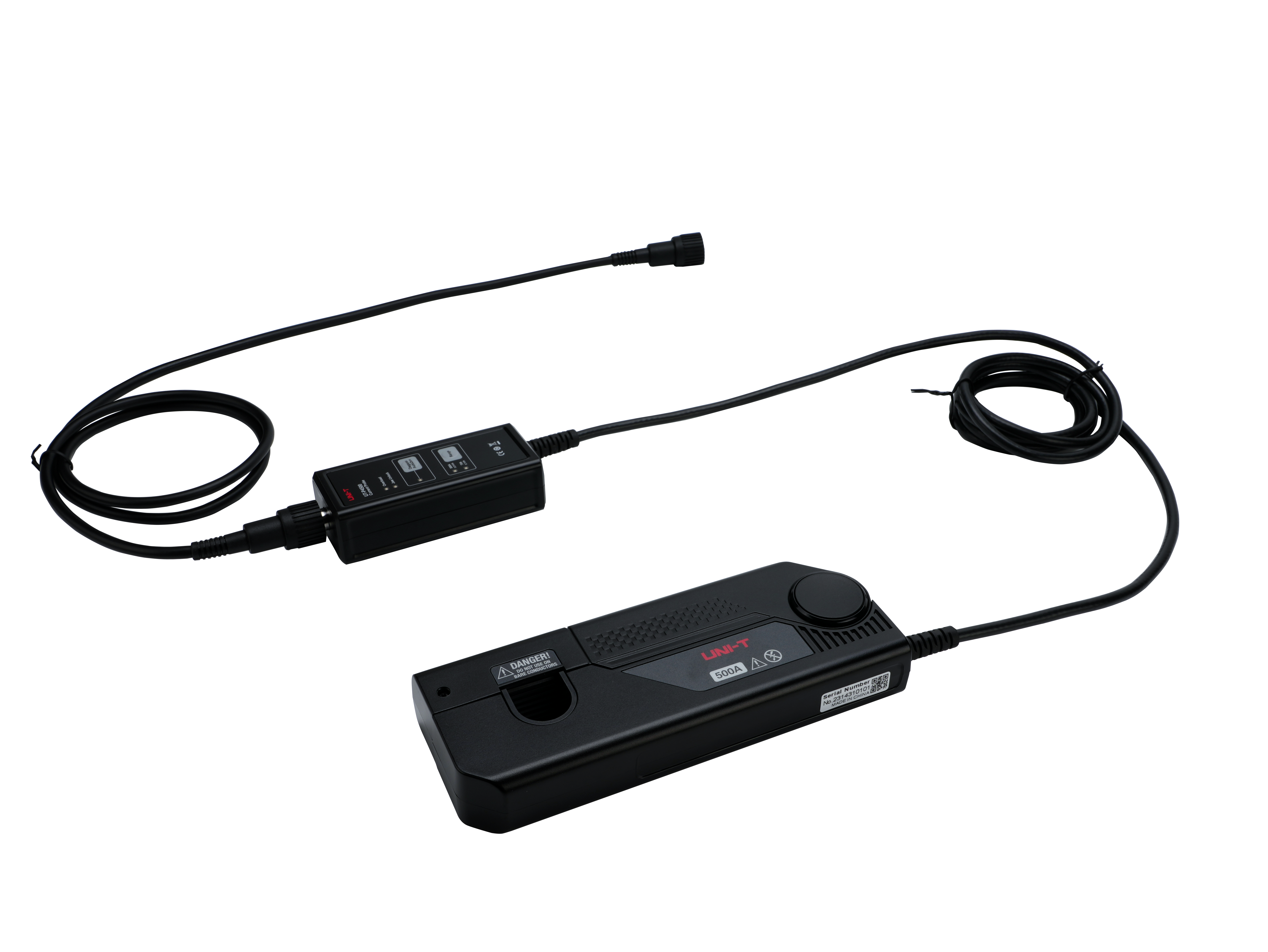 UT-P4500
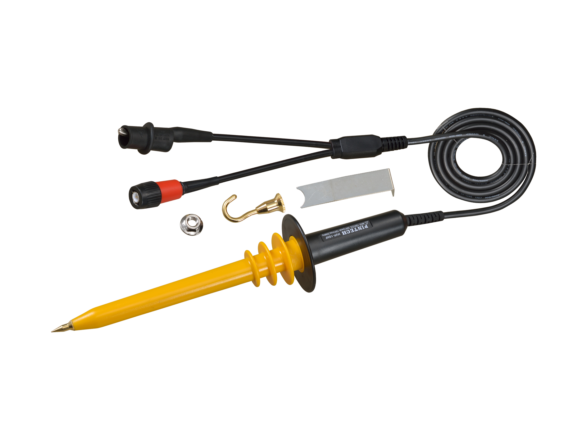
 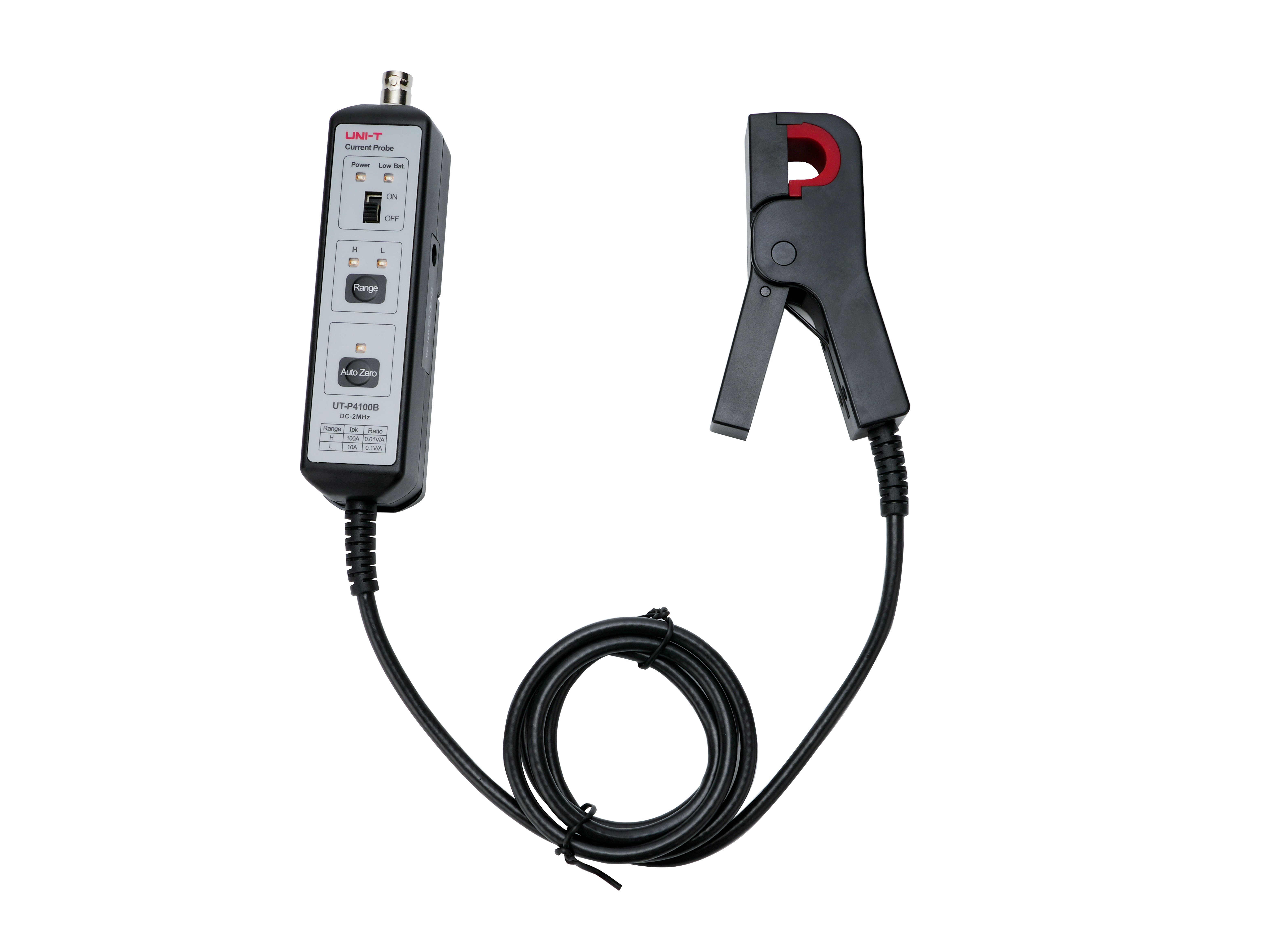 UT-P4100B
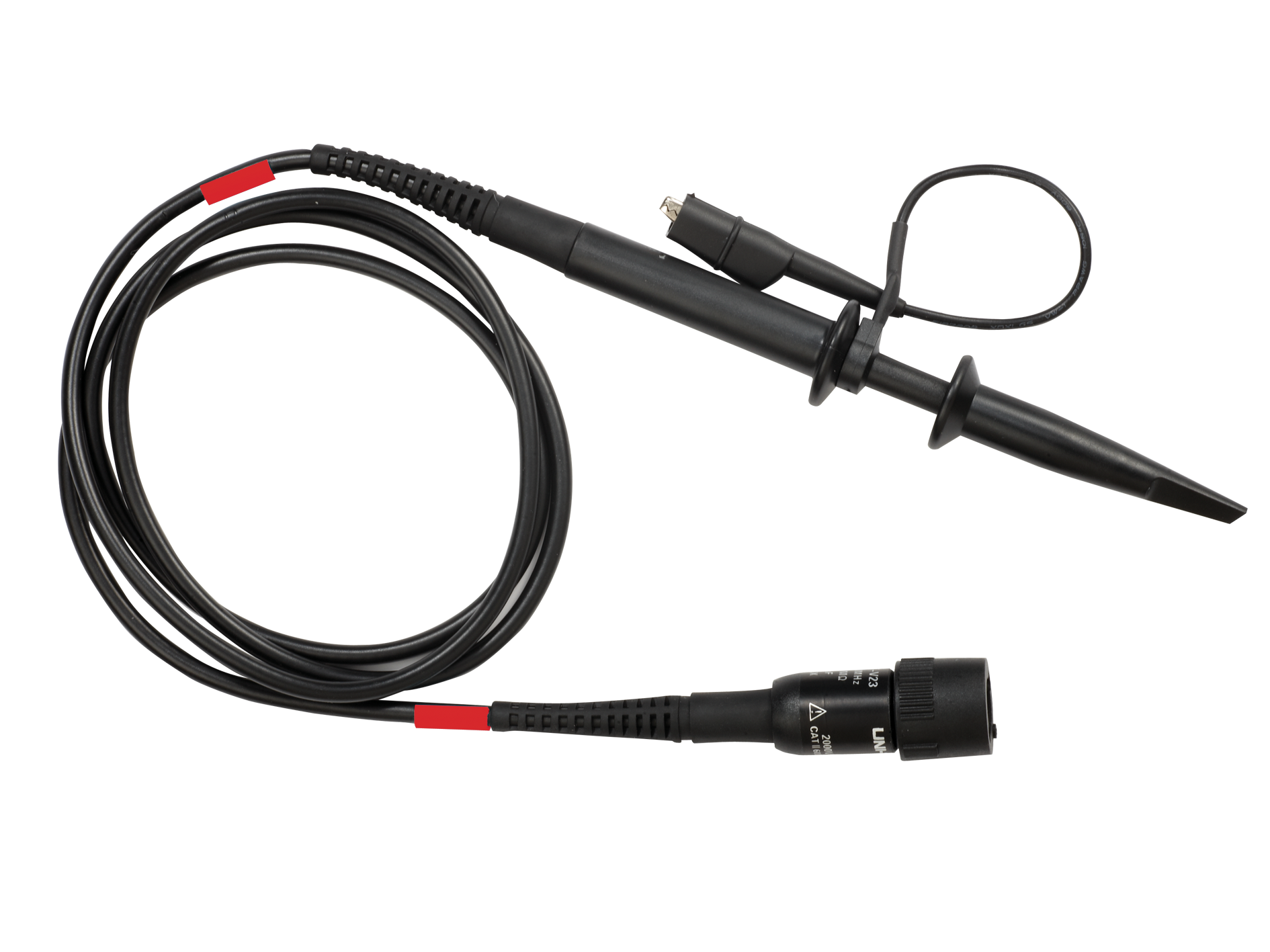


